Kyber is the successor to NVIDIA’s Oberon rack design for its scale-up GPU configurations. It will first appear for VR300 NVL576.1
2026-era Kyber design
NVIDIA showcased an updated Kyber rack design at GTC26. The following is from my GTC26 recap blog.
Each Kyber rack has the following:
- 2x compute chassis per rack
- 18 compute sleds per chassis
- 36 sleds per rack
Each compute sled has:
- 4 SSDs
- 2 (or 4?) NICs
- 4 GPU sockets
- 2 CPU sockets
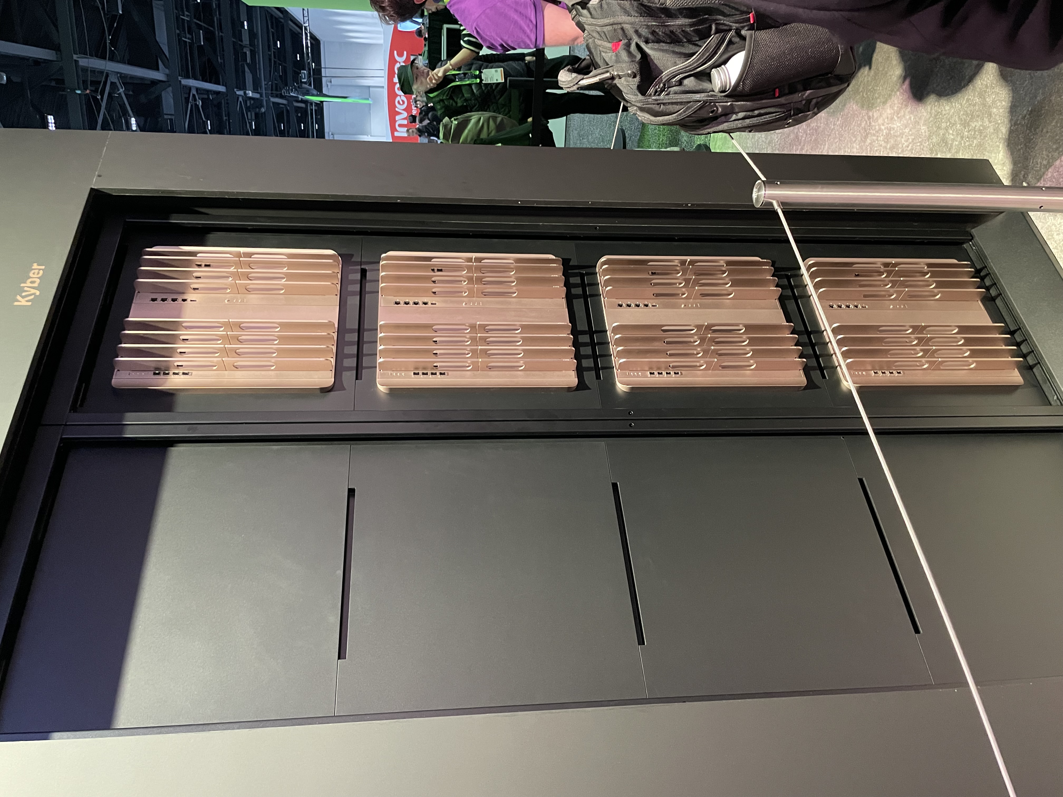
Here is the front of the Kyber rack, showing two compute chassis, each with 18 sleds.
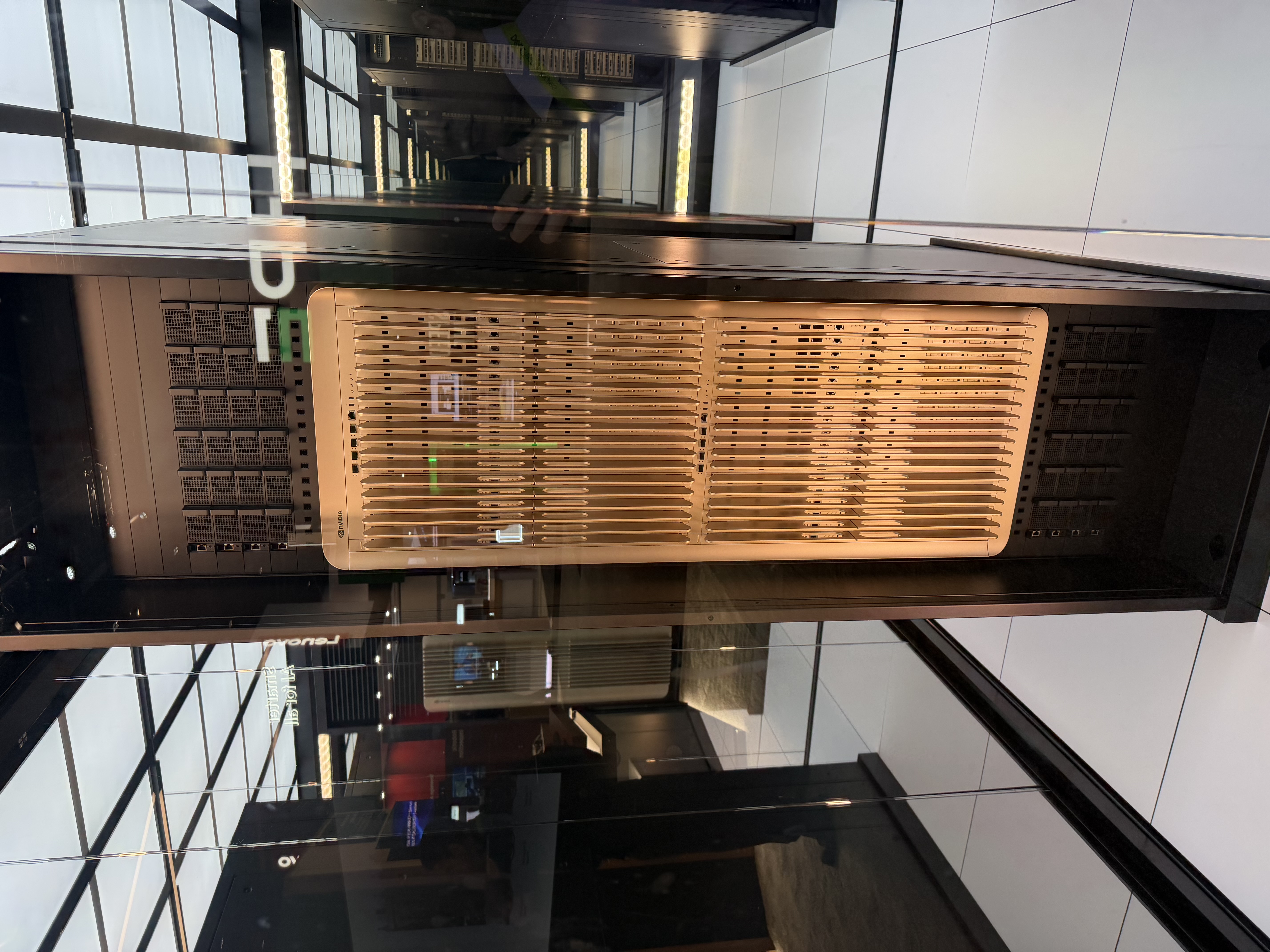
NVIDIA did not restate this new Kyber rack’s power requirements, but this display unit appears to have 8x power shelves (or steppers, or power stabilizers, or something) integrated into it.
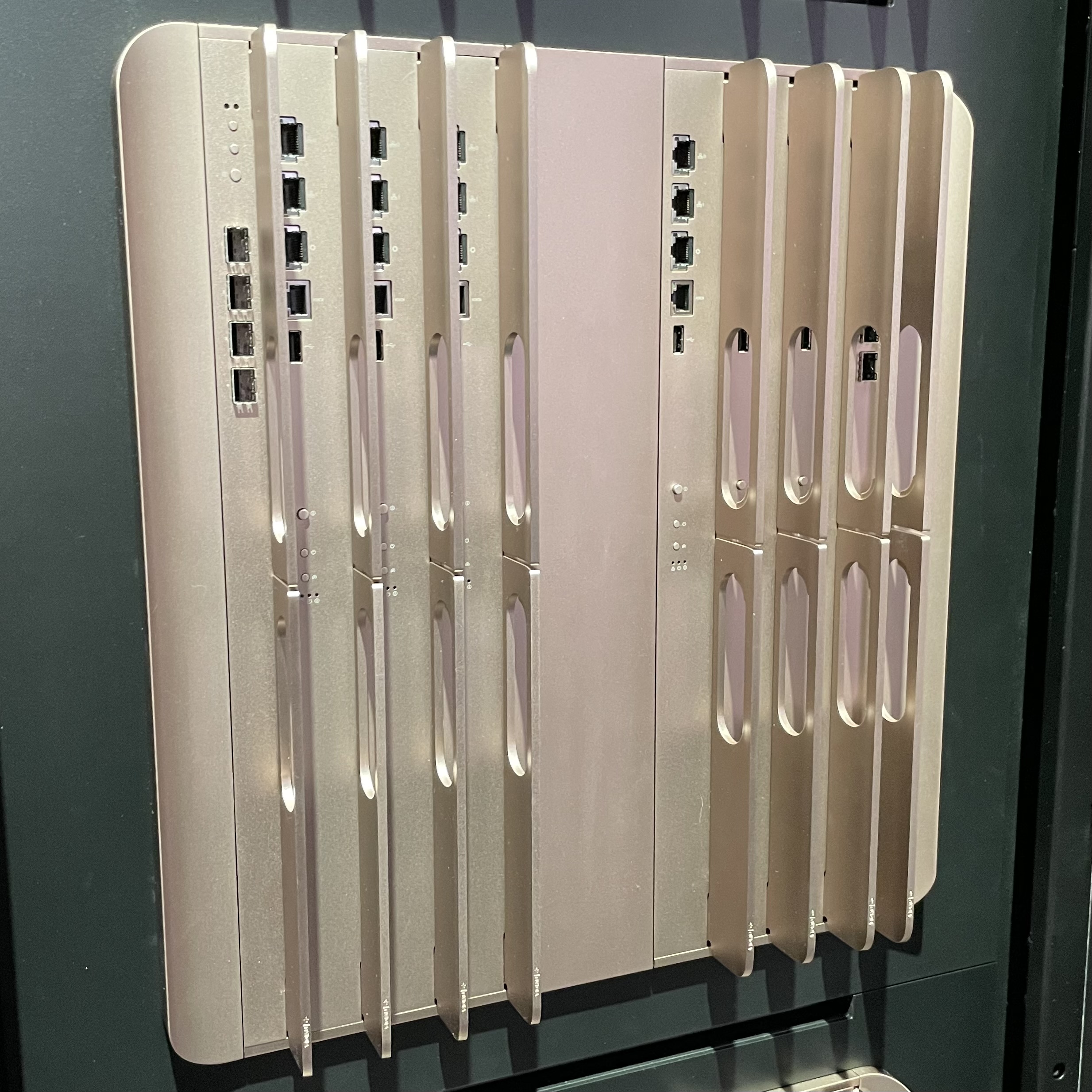
The compute trays are shown below; a lidded version was on display (left), and Jensen showed an unlidded version during his keynote (Right):
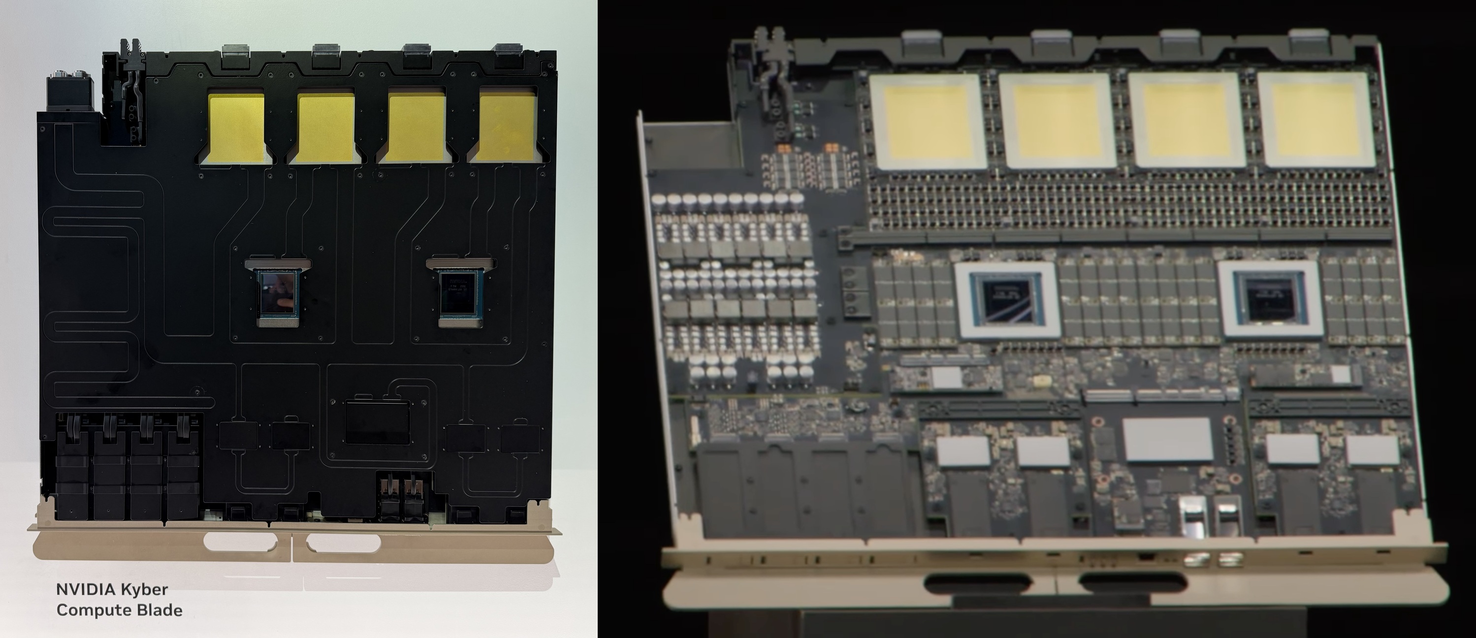
They contain 2 Vera + 4 Rubin Ultra ratio, and a lot of space is taken up by Vera’s SOCAMM memory modules and VRMs. In addition, there appear to be 4x NIC ASICs which are connected to weirdly small front-facing ports along with one big NIC ASIC which serves two bigger OSFP-looking ports.
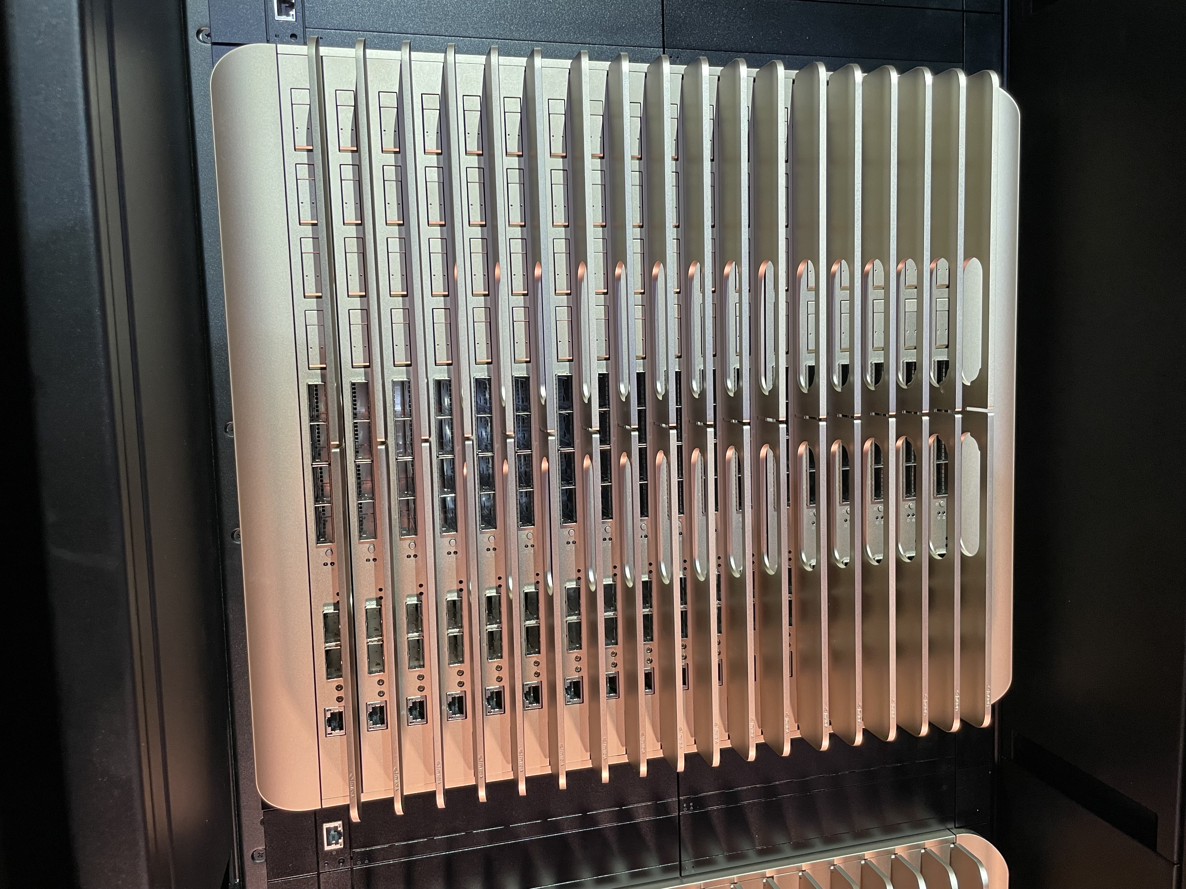
The NVLink backplane is physically integrated as a rear-facing, monstrous NVLink Switch tray that acts as both switches and cable backplanes:
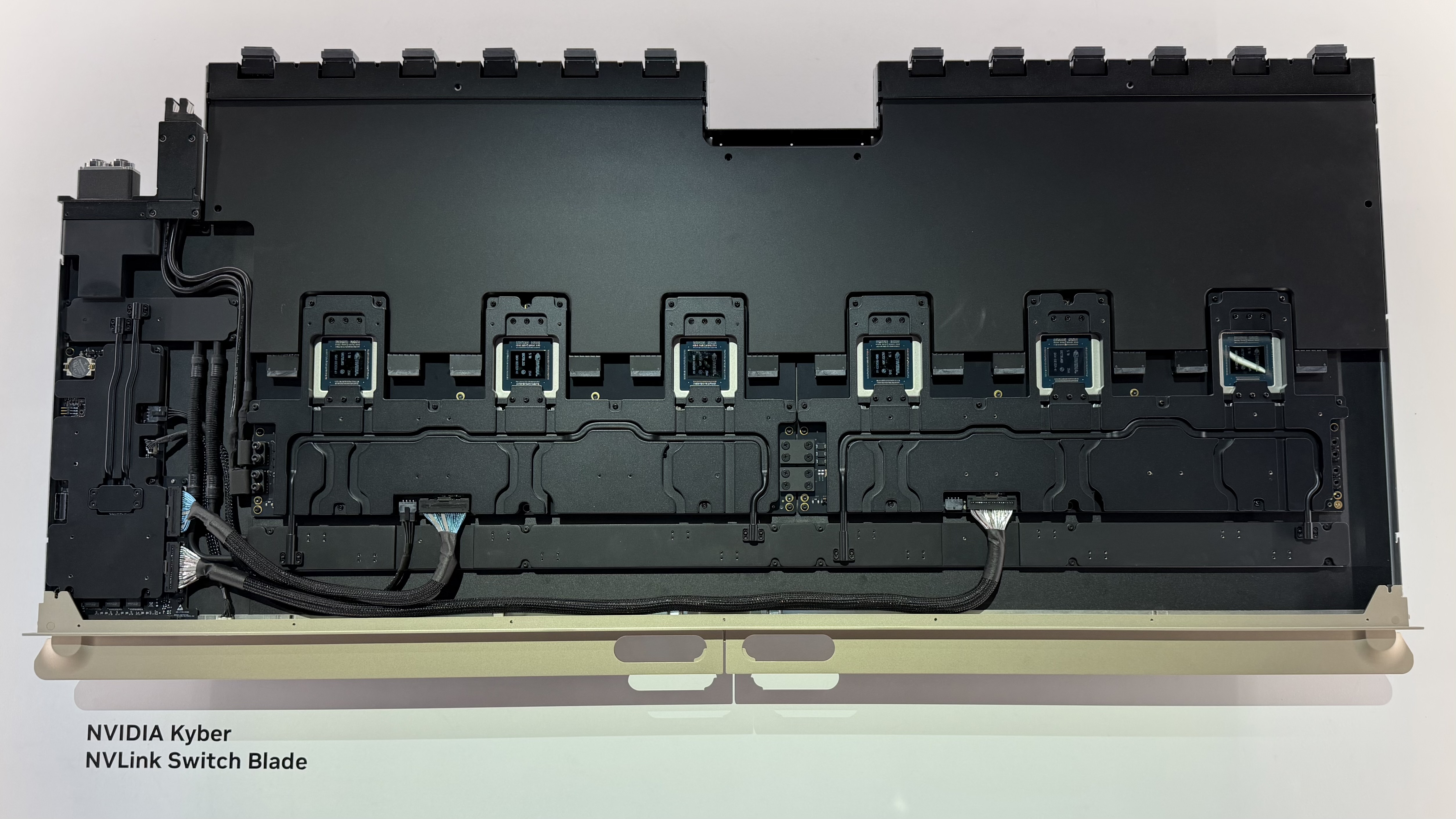
This huge blade connects two midplanes (and their 18x compute trays) together within a rack through 6x NVLink 7 switches. My guess is that 36 compute trays on the front will be matched by 6x of these NVLink Switch trays to enable all-to-all connectivity across the NVL144 domain.
Power infrastructure
Kyber initially launched as a 600 kW rack with 72 compute sleds per rack at GTC25, but the design at GTC26 appeared to have lost half its GPU density. It remains unclear if this new Kyber is now a 300 kW rack.
NVIDIA revealed their goal to develop 800 VDC row-scale power distribution to power these Kyber racks at COMPUTEX 2025,2 and mulitple vendors were showcasing these solutions at GTC26. This is a 800V DC power sidecar that APC had on display:
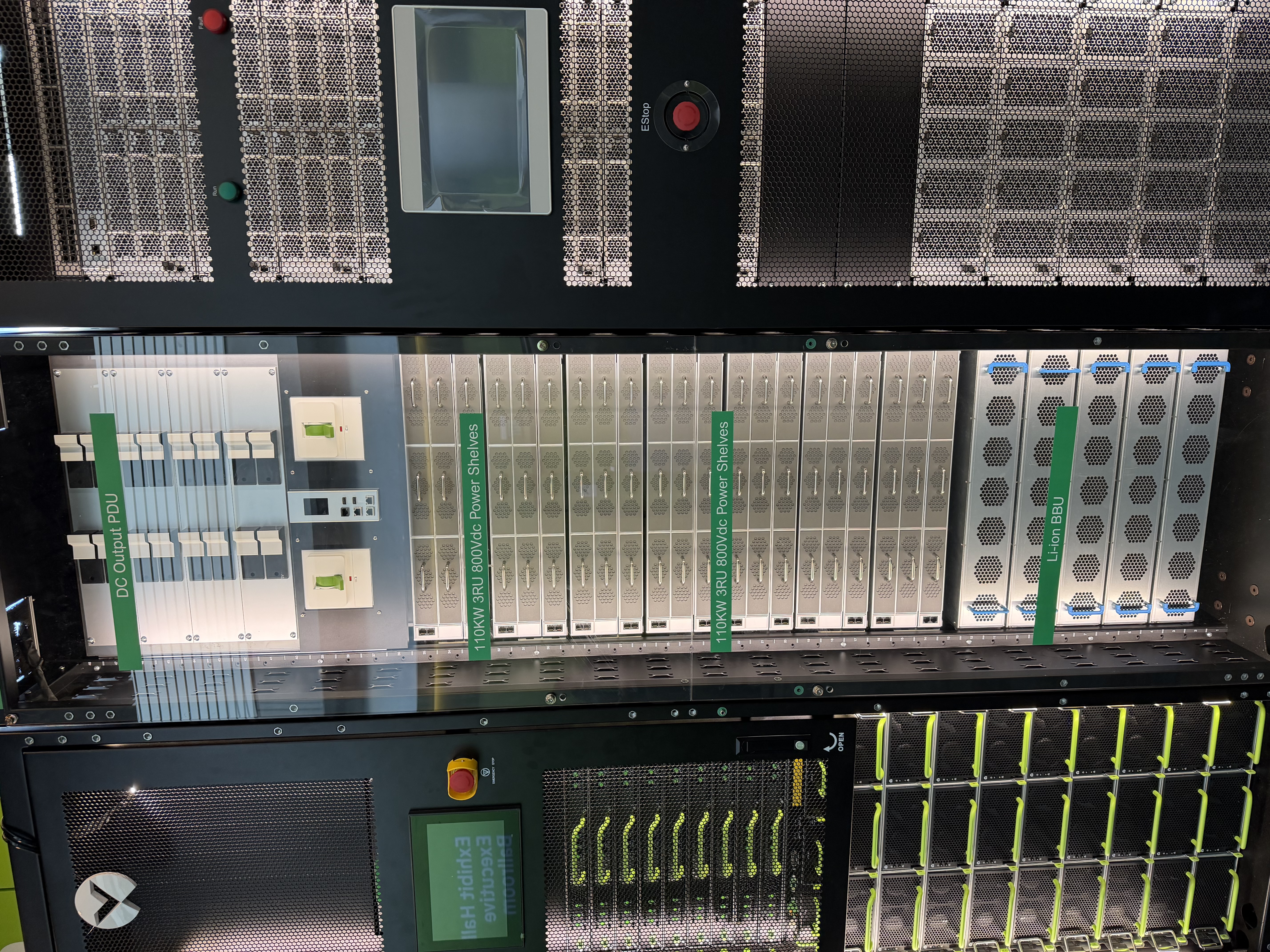
These sorts of power racks will live alongside every Kyber rack. This display model had the following components:
- 4x 2U “DC Output PDUs” - These look like they provide circuit protection for the 800V outputs that go over to the GPU rack. Maybe the throw switches are breakers?
- 4U power management controller with manual disconnects? Maybe one per zone?
- 7x 3U “110KW 3RU 800Vdc Power Shelves” - The things that do the actual work. Assuming 6+1, this is enough power for the original 600 kW Kyber rack.
- 5x “Li-ion BBU” - Battery backup units. These are less about allowing GPUs to ride through power outages and more about protecting upstream electrical gear from the high-frequency oscillations caused by 144 Blackwell Ultra GPUs synchronously switching on and off during training.
2025-era Kyber prototype
The first Kyber prototype debuted at GTC25 as a 600 kW compute rack with a second sidecar rack to handle power and cooling.3
The following commentary about the Kyber rack comes from photos I took at GTC25 and my subsequent GTC 2025 Recap blog post.
At a glance, each Kyber rack has four compute chassis, each with
- Eighteen front-facing, vertically mounted compute blades. Each blade supports “up to” sixteen GPUs and two CPUs each. I presume a “GPU” is a reticle-limited piece of silicon here.
- Six (or eight?) rear-facing, vertically mounted NVLink Switch blades. All GPUs are connect to each other via a nonblocking NVLink fabric.
- A passive midplane that “eliminates two miles of copper cabling.”
Here is a photo of the rear of a Kyber rack, showing all four chassis:
Examining one of those chassis closely, you can see two groups of four blades:
Six of these blades are identical NVLink Switch blades, but it wasn’t clear what the other two were. It looks like the odd two blades have SFP+ ports, so my guess is that those are rack controller or management blades.
The front of the Kyber rack shows the row of eighteen compute blades in each chassis:
Given there are four chassis per rack, this adds up to 72 compute blades per rack and NVLink domain. This means there are 8 GPUs per compute blade; given that Rubin Ultra will have four GPUs per package, it follows that each compute blade has two GPU packages. However, a placard next to this display advertised “up to 16 GPUs” per compute blade, so I’m not sure how to reconcile those two observations.
From the above photo, you can see that each blade also has front-facing ports. From the top to the bottom, there appear to be
- 4x NVMe slots, probably E3.S
- 4x OSFP cages, probably OSFP-XD for 1.6 Tb/s InfiniBand links
- 2x [cables and connectors|QSFP-DD] ports, probably for 800G BlueField-4 SuperNICs
- 1x RJ45 port, almost certainly for the baseboard management controller
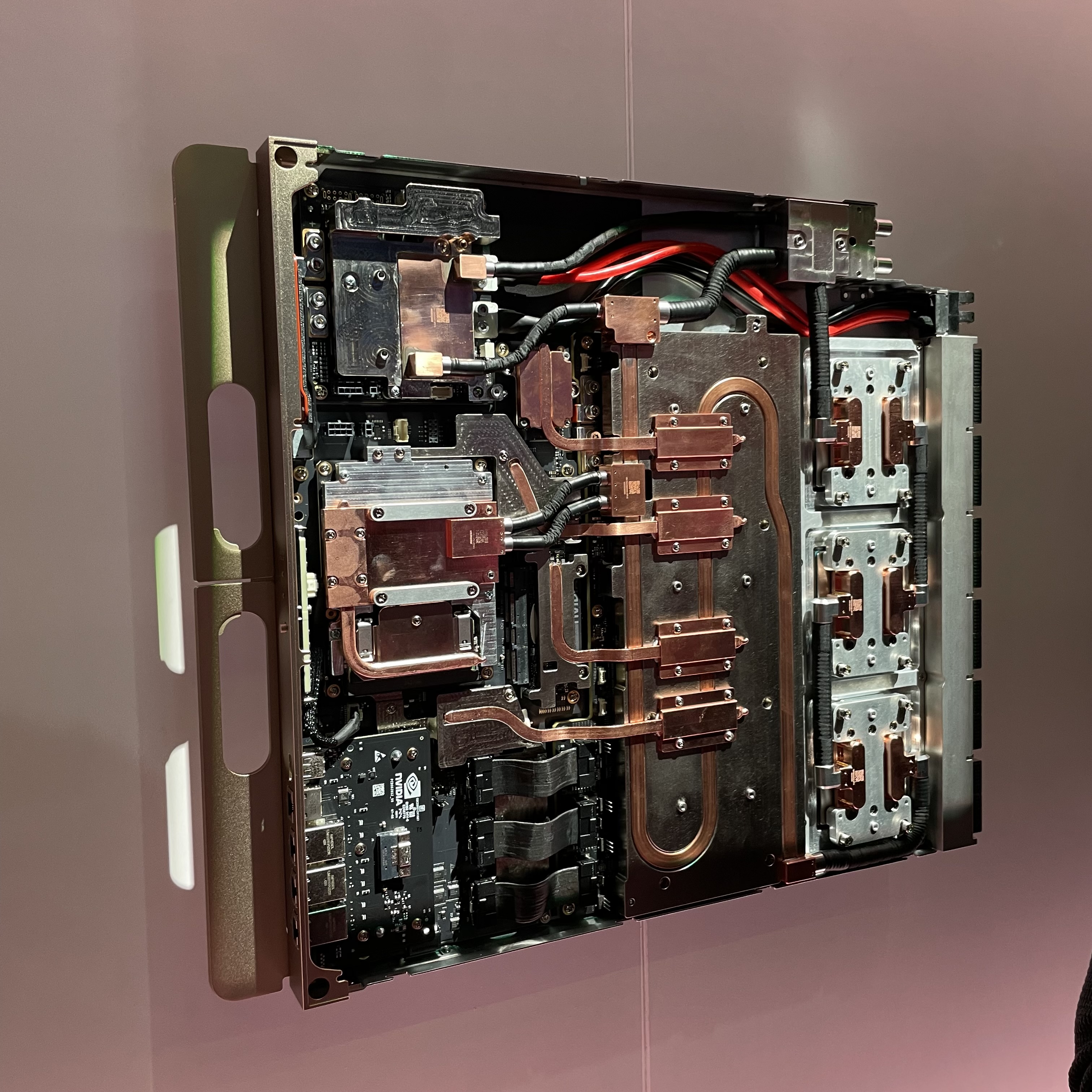
NVIDIA also had these blades pulled out for display. They are 100% liquid-cooled and are exceptionally dense due to all the copper heat pipes needed to cool the transceivers and SSDs:
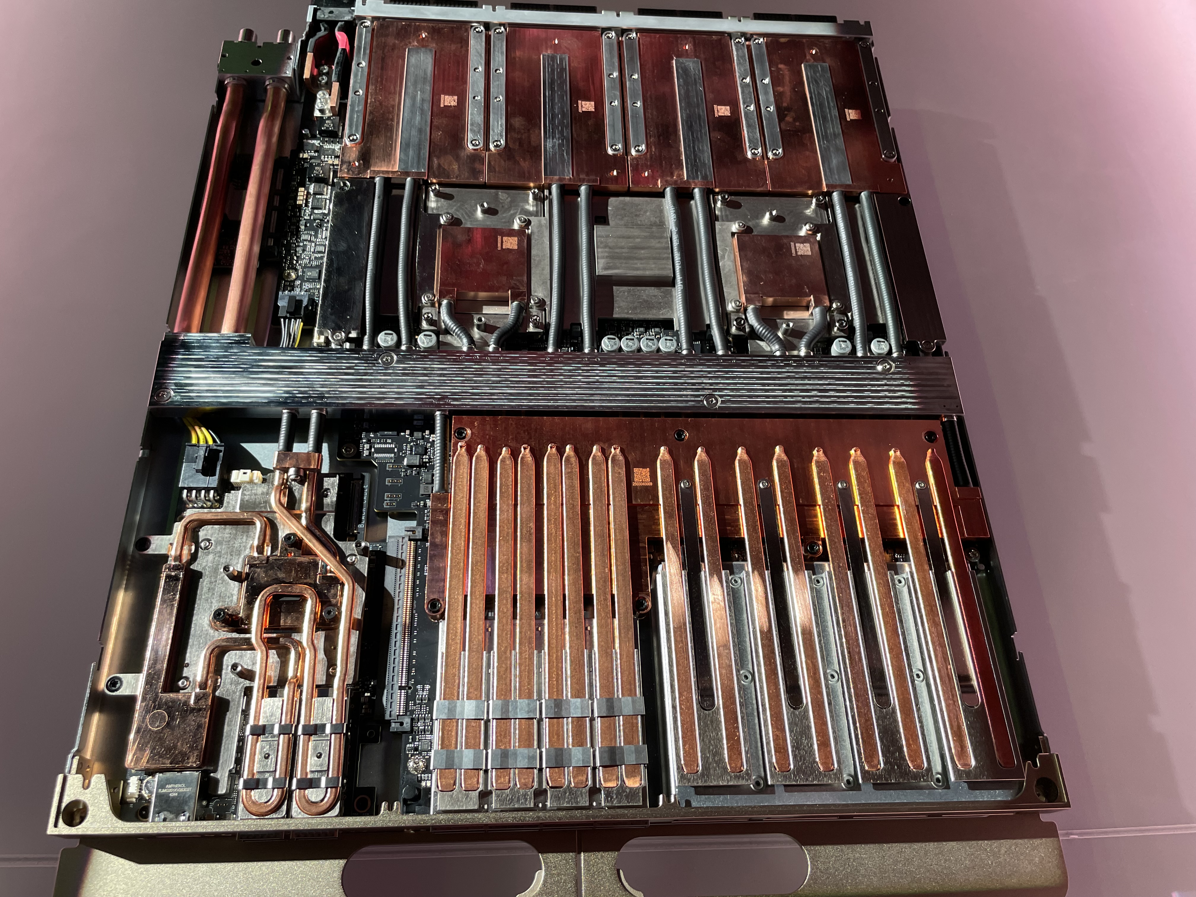
The front of the blade, with the liquid-cooled SuperNIC (top), InfiniBand transceivers (middle), and SSDs (bottom), is on the left. Four cold plates for four Rubin GPUs are on the right, and two cold plates for the Vera CPUs are to the left of them. I presume the middle is the liquid manifold, and you can see the connectors for the liquid and NVLink on the right edge of the photo.
A copper midplane replaces the gnarly cable cartridges in the current Blackwell-era Oberon racks:
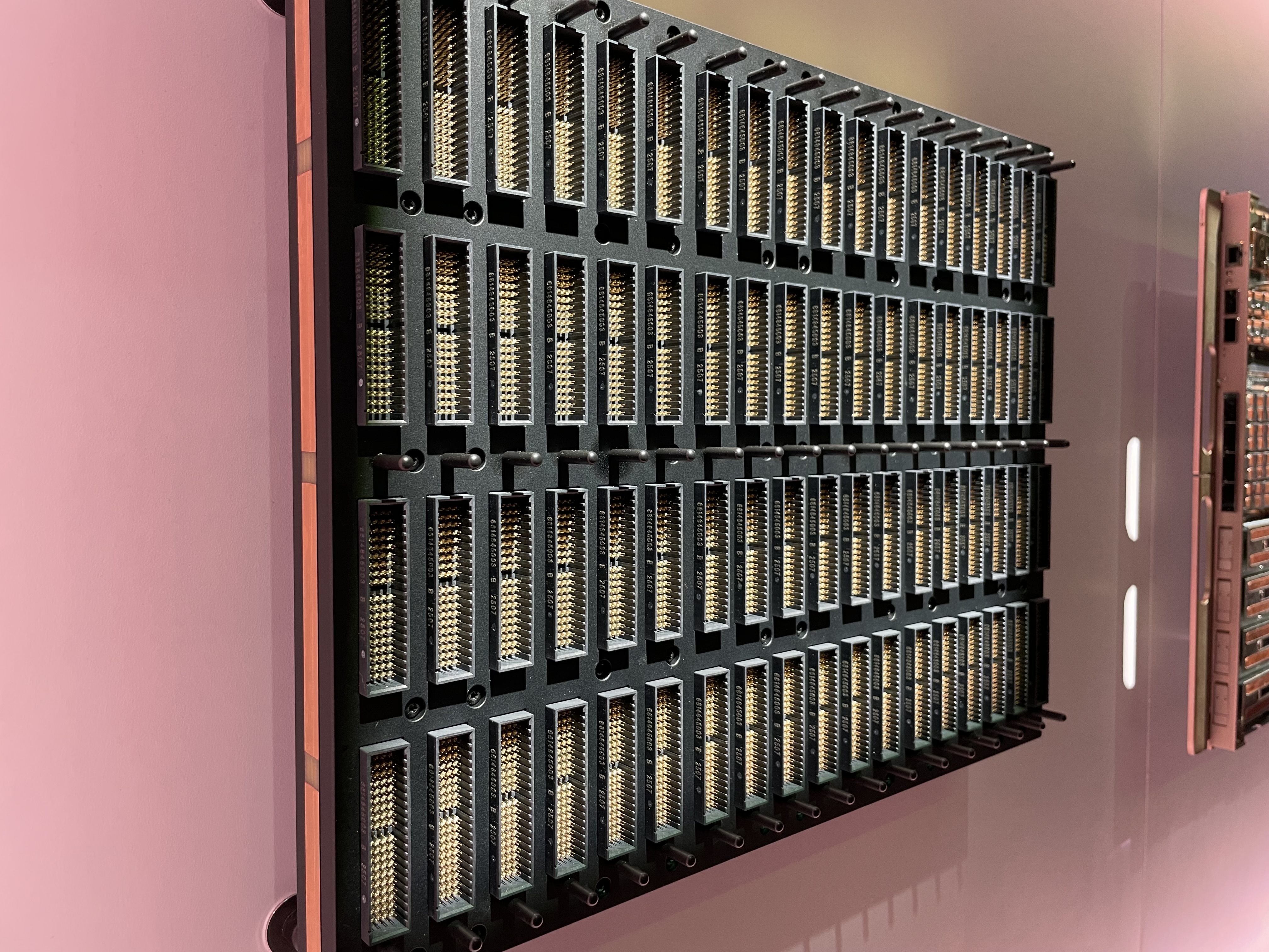
This compute-facing side of the midplane has 72 connector housings (4 18), and each housing appears to have 152 pins (19 rows, 4 columns, and two pins per position). This adds up to a staggering 10,000 pins per midplane, per side. If my math is right, this means a single Kyber rack will have over 87,000 NVLink pins.
Although the midplane has cams to help line up blades when they’re being seated, these sorts of connectors freak me out due to the potential for bent pins. Unlike Cray EX (which mounts compute blades at a right angle to switch blades to avoid needing a midplane entirely), Kyber mounts both switches and compute vertically. This undoubtedly requires some sophisticated copper routing between the front-facing and rear-facing pins of this midplane.
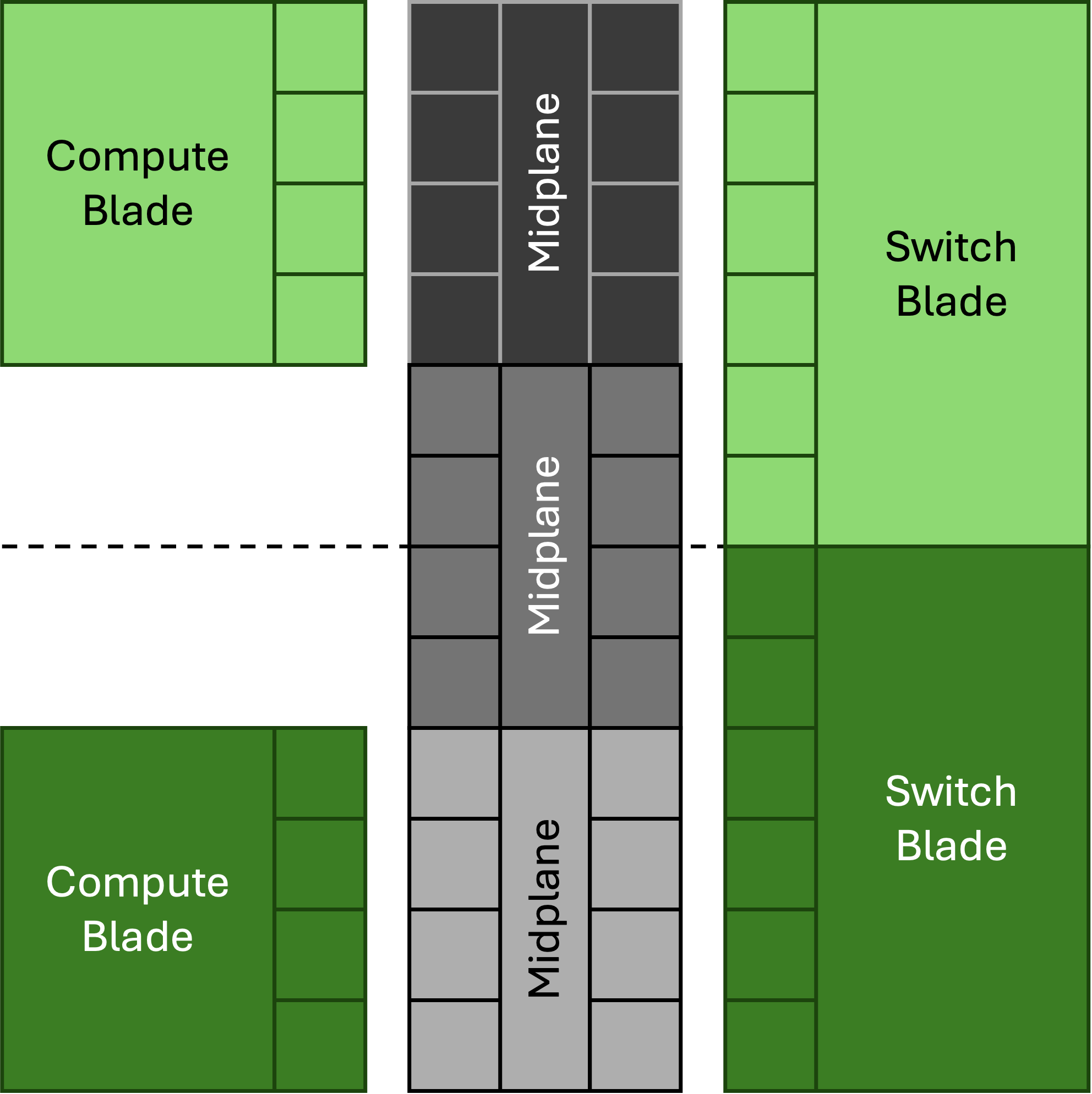
It’s also unclear how NVLink will connect between the four chassis in each rack, but the NVLink Switch blade offers a couple clues on how this might work:
Each switch blade has six connector housings on the right; this suggests a configuration where midplanes are used to connect to both compute blades (with four housings per blade) and to straddle switch blades (with two housings per switch):
Here is some commentary that resulted from my GTC recap posted to Substack:
From Tanj
On the network blade the 6 connectors are not the same size each as the 4 connectors on the GPU blade. Also there are 6 switch blades for 18 GPU blades? That suggests the connectors are a different density - double density and 1.5x number of connectors?
Reply from amnon izhar:
the GPU sleds are slimmer and only show 4 diff pairs per row vs the switch sleds are thicker can support 8 diff pairs per row. The 1.5 multiplier is because the switch blade shows 3 NVlink switch per blade vs the current NVL72 that supports 2 NVLink switches per sled.