Introduction
In a previous page, I described how we could characterize bipolar junction transistors using a potentiometer and a multimeter using a simple test circuit. However, there were two aspects to that experiment which were very tedious:
- turning the potentiometer to set different Vbase values over and over
- clipping the voltmeter to different leads to take different measurements for each potentiometer setting
With the Raspberry Pi's GPIO, a few simple integrated circuits, and a little Python, it's actually quite simple to automate this entire experiment. Specifically, we can replace
- the mechanical potentiometer with a digital potentiometer (digipot) such as the MCP41010 digital potentiometer chip
- the digital multimeter with a analog-to-digital converter (ADC) such as the MCP3008 analog-to-digital converter chip
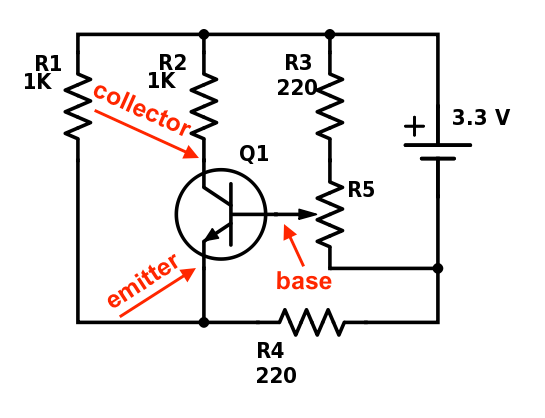
The following guide repeats the experiment on my page on understanding bipolar junction transistors where we built the following circuit:

and measured the voltages at the three taps shown to get Vcollector, Vbase, and Vemitter. For this set of experiments though, we will replace R5 (a standard potentiometer) with a digital potentiometer, and replace our red multimeter taps with an ADC.
Digital Potentiometers
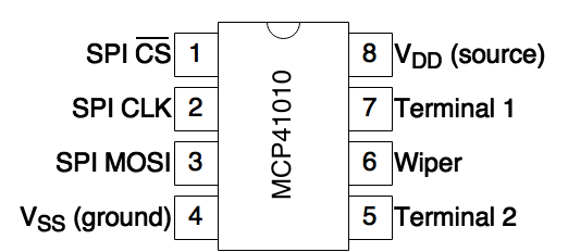
The digital potentiometer, which we'll abbreviate as digipot, is a very simple integrated circuit that behaves exactly like a regular (mechanical) potentiometer in that it has two terminals (usually connected to a source and ground) with a wiper terminal in between that outputs the variable resistance. The MCP41010 that I use is pinned as follows:

Pins 5, 6, and 7 are connected exactly the same way as the three pins on a regular potentiometer, and VSS and VDD are connected to ground and the 3.3 V source on the Raspberry Pi GPIO pins.
To program the MCP41010 (that is, to set the resistance you want it to have), you send it 16-bit SPI packets not unlike I discuss on my MAX7219 page. These packets have the format:

where
- Command is
0001to set a new resistance value0010to put the chip in shutdown mode
- Channel determines which wiper to modify. Since the MCP41010 has only one
channel, this value should always be
0001. - Value is the 8-bit to use as the resistance. Since my MCP41010 was a 10
KΩ potentiometer,
00000000(0) = 0 ohms11111111(255) = 10,000 ohms00010011(19) = 19 / 255 × 10,000 = 745 ohms
So for example, setting a resistance value of 745 ohms would involve
- Pulling CS low to initiate a transmission
- Pull MOSI low, then CLK high, then CLK low to send a zero (this is the most
significant bit). Repeat two times to send the first three bits of the
Command packet (
000) - Pull MOSI high, CLK high, CLK low to send the 4th bit of the Command packet
- Continue to send the Channel portion,
0001, as we did in steps #2 and #3 above - Continue to send the value (
00010011) - Pull CS back high to end transmission
After CS is raised high again in step #6, the wiper pin should demonstrate a resistance of 745 Ohms.
Analog-to-Digital Converters
Analog-to-digital converters (ADCs) are essentially voltmeters that can report what the voltage is between a sensor pin and a reference voltage. The MCP3008 chip we'll use measures the voltage with reference to VSS (ground) with 10 bits of accuracy, and it has eight channels that provide independent sensor pins.
The MCP3008 has a 16-bit SPI packet structure not unlike the MCP41010:

Unlike the digipot, though, communicating with the chip involves both writing commands (which I consider input) and reading back the result (output). Specificially,
- The two most-significant bits represent the command to issue; we want to
measure voltages with respect to ground, so we will use the
11command to inidicate "single-ended" mode. - The next three bits are used to select from which of the eight channels
(
000= 0 through111= 7) we wish to read a measurement. - The sixth bit is a "don't care" bit; we just pulse the clock signal.
- The last ten bits are the measurement that the ADC returns to us; this
value will range from
0000000000(0) to1111111111(1023), which correspond to zero volts (0) to the reference voltage (1023, or 3.3 V). When reading these bits from the MISO (output) pin, the MOSI (input) bits are considered "don't care" bits.
Adafruit has a great tutorial on the MCP3008, that provides a more thorough overview of exactly how to wire up this chip, so I won't cover the pinouts here.
All-digital transistor test circuit
Armed the MCP41010 digipot, MCP3008 ADC, and a reasonable knowledge of how to program them via SPI, it's quite simple to fully digitize the transistor test circuit.

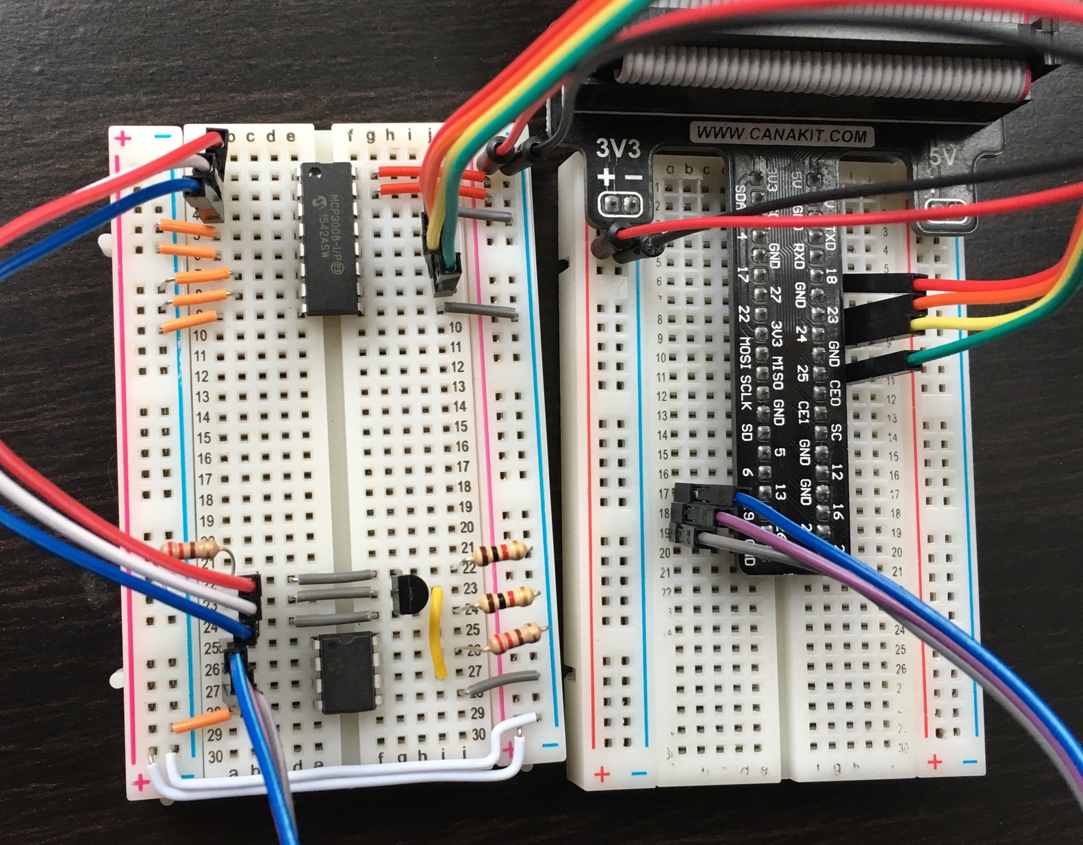
In the above photo, the MCP3008 ADC is in the top half of the breadboard, and it has red/orange/yellow/green cables connecting it to the Raspberry Pi for SPI on its right side. On its left side are red/white/blue sensor cables that connect to the 2N2222's emitter, base, and collector; the short orange cables are just grounding the remaining un-used sensor pins.
The bottom half of the breadboard contains the MCP41010 digital potentiometer instead of the blue rotary potentiometer, but is otherwise the same. There is a patch of new cables (blue/purple/grey) that connect to the Raspberry Pi for SPI control of the MCP41010, and instead of red/black alligator clips, we now have sensor cables that connect to the MCP3008.
Once this is all wired up, re-running our experiment is a rather straightforward matter of
- setting the digital potentiometer
- reading the values off of each channel of the analog-digital converter
- repeating
In Python and using my basic SPI library, it would look something like this:
#!/usr/bin/env python

"""Vary resistance on a digital potentiometer and measure the effect using
   an analog-digital converter"""
import spi # from https://github.com/glennklockwood/raspberrypi
import time

# use two independent SPI buses, but daisy chaining then is also valid
adc = spi.SPI(clk=18, cs=25, mosi=24, miso=23, verbose=False)
digipot = spi.SPI(clk=19, cs=13, mosi=26, miso=None, verbose=False)

# iterate over all possible resistance values (8 bits = 256 values)
for resist_val in range(256):
    # set the resistance on the MCP41010
    cmd = int("00010001", 2)
    # make room for resist_val's 8 bits
    cmd <<= 8
    digipot.put(cmd|resist_val, bits=16)

    # wait to allow voltage transients to subside
    time.sleep(0.2)

    # get the voltage from the MCP3008
    voltages = [0, 0, 0]
    for channel in range(len(voltages)):
        # set the start bit, single-ended mode bit, and 3 channel select bits
        cmd = int("11000", 2) | channel
        # read 1 null bit, then 10 data bits
        cmd <<= 10 + 1
        value = adc.put_get(cmd, bits=16)
        # mask off everything but the last 10 read bits
        value &= 2**10 - 1
        voltages[channel] = 3.3 * value / 1023.0

    # 10000.0 because MCP41010 is a 10 Kohm digital pot
    print "%4.2f %4.2f %4.2f %5d" % (voltages[0], voltages[1], voltages[2],
                                     10000.0 * resist_val / 255.0)
Not only is this much faster than turning a potentiometer by hand and reading off a voltmeter, it gives much more precise data:

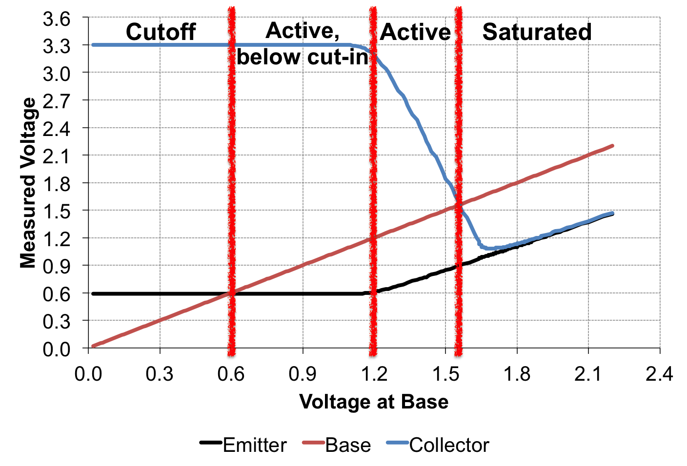
The above plot represents measurements for all 256 possible resistivities that the MCP41010 can provide. The linear relationship between the voltages is clearly shown with very little noise in the data, showing that using an ADC and digital potentiometer with Raspberry Pi is a very precise way to characterize the behavior of transistors.
Going forward
Combining a digital potentiometer and an analog-digital converter with Raspberry Pi provides a fast, precise way to experiment with transistors. Using a little bit of Python, we were able to change the input voltage going into a component we didn't understand very well (the 2N2222), and could then measure the effect on its outputs. While we did this for a simple NPN transistor in this experiment, the same technique and software can be used to examine more complicated circuits like logic gates and pulse shaping circuits.
To simplify the process of writing more elaborate experiments, I've created a a very simple MCP41010 Python class and MCP3008 Python class, both based on my SPI class, that provide a single command to set a resistance value or get a voltage reading. I also wrote a more sophisticated version of this transistor test to show how these classes can be used to simplify experiments using an ADC, digipot, and Raspberry Pi.